Here is the video, finally completed.
Its missing closeup footage of me prying the LCD plates apart but i included some photos instead, i was supposed to use my go pro but when the time came i couldnt find it. Also its not a true start to finish since i began with a monitor with the tape cut/ removed and i already removed the CCFLs a while ago, but, both those are trivial processes, just cut the tape and peel the kapton holding the CCFL holder in place. Anything else you can read about in prior entries.
This video took hours to encode and to retain quality i couldnt have the end file size less than 700mb so, theres a few minor issues here and there i would have liked to have removed, like text which is too close to the borders, but, given the time it takes and the uploading data, and time (i have slow upload rates), this should be good enough, though, i will also be re-encoding in 720p and dropping the bitrate, and uploading the original video to my mega cloud for anyone to view offline.
Soon ill also be posting the video where i observed the maximum input for the strips, which i later managed to confirm was true when i discovered how to find out LED specs.
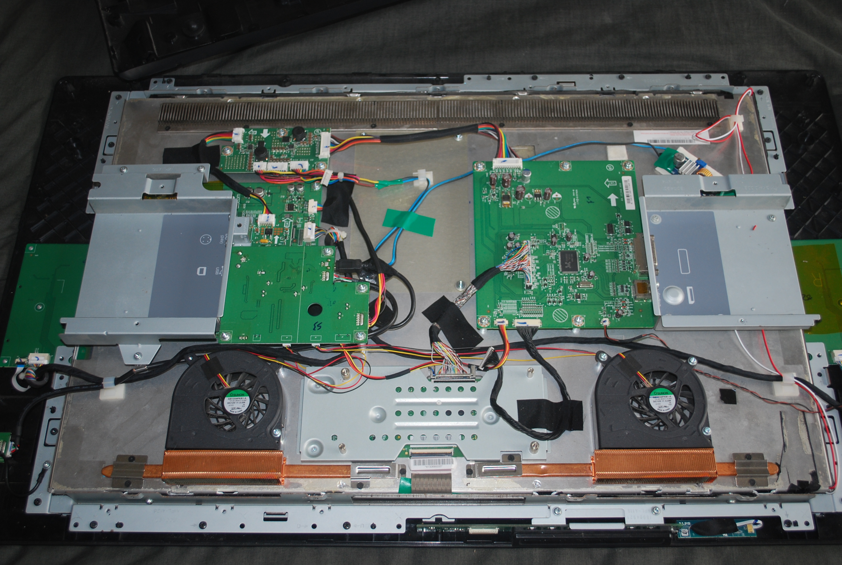
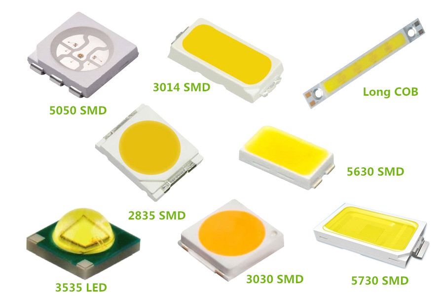
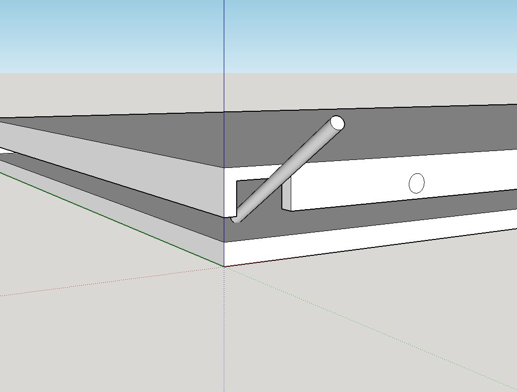
Heres a dump of related images that you might find handy when doing your own repair using the video for a reference:
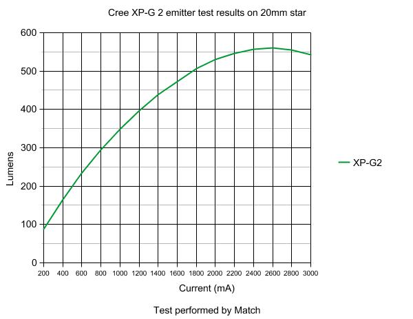
Note this graph is not for the LED strips, its just an example of the relationship between LED power input and light output, where light output actually decreases after the maximum current is exceeded.






Normally I do not read post on blogs, but I would like to say that this write-up very compelled me to try and do it! Your writing style has been surprised me. Thanks, very nice article.
What are the benefits of the Wacom Color Calibration software included with the Cintiq 24HD touch and how does it work?
im not too familiar with any specific software for color calibration, but if its a thing its probably because the tint of CCFL tubes changes over time, skewing the pallet, which can be important for art as you might imagine, that you have the ability to make your colors dead on and not just look like they look only on your screen but on everyone elses
Hey there,
My friend’s Wacom cintiq 24hd display broke and they’re trying to find a replacement part which we’re struggling to find. When I searched the image of the part it brought me to your blog. I was hoping you could help point me in the right direction buy at least helping me determine the name of the part. I would be very grateful! I can email you the photo of the part.
send me the details in the discord chat, a link to it is at the top of the page
Hi Ronox!
You’re the best! I followed your instructions and the LED backlight works. But the screen is displaying pixels from my computer super weirdly now, looks very glitchy and low-detail. Here is a video of the effect : https://www.dropbox.com/s/8ygo89udx24yx4s/VID_20200322_173839817.mp4?dl=0
I know this might be totally unrelated problem, but I’m not sure who else to ask.
Does this look any bit familiar to you, or do you have any idea what might cause it? Did I mess up something inside or is it an issue with the video connecter? Oh, and it might be relevant that I made a huge crack in the screen in the process of repairing the backlight.
Thank you!!!
sorry about the late reply, could you reupload/relink that? it appears to have expired.
Ill take a wild guess and, is it looking like every second row of pixels is either not there?
alternatively send me a pic on my discord server, ill get notified right away
Hi (Hopefully you are still around and able to maybe answer some questions)
My 24HD needs backlight replacement. Powers on, fans blow, desktop visible for a fleeting moment, then dark screen with powered lights still glowing. (verified backlight issue by using flashlight> Image is visible behind screen when angling light)
This monitor clearly out of warranty. And I think only if you live in Japan next to the Wacom factory is it feasible to have them repair it.
So, I am not afraid to tackle replacing the lights with LEDs. But, I am not at all electronically gifted in lingo or knowledge, so I am a bit lost.
Your video is awesome and definitely helps build confidence for disassembly. (Thank you very much for taking the time to make the video and edit it)
Ok>>>
I’m guessing that when I remove the original ‘tube lights’ they will be connected to one of the boards inside the Cintiq where they are getting powered.
The new LED lights are individually wired per strip and plug into a supplied “board” . The board then has one lead connector coming from it. >>I am assuming this lead connector will possibly plug into where the original ‘tube lights’ had been plugged into on one of the Cintiq boards to get powered ?
Then I simply use all 1500 screws to put it all back together and plug it in and everything is working again?? (I have a feeling the answer is “no” because things are never that simple.)
So, what is this XL-4015 thing ? (Does it replace the ‘board’ that the new LEDs come with??)
Do I put a 12volt power supply into one side of the XL4015 (from somewhere in the Cintiq. And then on the output side I clip the LED wires and put them in here?
I’m very mechanically inclined but I know nothing about circuitry.
Any way you could explain this to me in simple terms so that I can proceed ?
Can you verify these items would be what I require to do this project ; ?
https://www.amazon.com/Adjustable-Step-Down-1-25-36V-high-Power-Efficiency/dp/B07RWKNR31/ref=sr_1_4?keywords=XL4015&qid=1568548876&s=industrial&sr=1-4
https://www.amazon.com/Highlight-Dimable-Backlight-Adjustable-Monitor/dp/B00XFXM4NA
Would I need anything else? A separate power supply ?? Anything ?
sorry about the late reply, yes, that is the correct stepdown converter. And that LED backlight, while not the best, will indeed work.
Also, yes, you unplug the inverter and use those power lines, use a multimeter to confirm however, you ONLY want to use the 24V lines, if you find a 12V line that is meant for fans only and is easily overloaded, and any 5v is a signal, plus you cant step 5v down to 9v, given that 5v is lower XD
Very few of the screws are completely neccesary unless you plan to say, ship the wacom somewhere, and need it to survive falling and etc.
Every time i open it up i end up with spare screws every single time. a few here or there doesnt matter, what matters is that you make sure to get the big structural ones all in for the main frame interface
Hello,
I have a doubt to connect the led, which color side tablet goes with what color side inverter ? on the inverter side i’ve 1 black 2 yellow and 1 red. on the tablet side i’ve 7 color : black, brown, red, orange, yellow, green and blue. (sorry for my english i’m french)
Thanks
I like what you guys are usually up too. This kind of clever work and coverage! Keep up the amazing works guys I’ve incorporated you guys to my own blogroll.
its just one person here but thanks 🙂
Hi! Again, many thanks for taking the time to answer my questions. When you replaced the power board on yours did you have to send it in or were you able to find one for it? Thanks ahead of time.
i never replaced the inverter, i repaired it, however the damage to the CCFLs was already done. As the tubes burn out, they remove the mercury vapors available, and turn it into something permanently solid like an oxide. So, eventually, even when the output is corrected, even when the vapors no longer build up only in one end, the vapor levels have dropped so much that even with perfect input they cant function anymore.
once i learned this, plus the fact the inverter was still discharging into the monitor, i decided to go for LEDs instead, which used a whole other driver
Hi
Thanks for this effort. I just bought a used 24HD ($450) that has the start up problem that I have worked around by warming it up the top and bottom edge, with a heat gun for a few mins before starting and then leaving it on once it is up and running.
I plan to order all the parts for repair and then pick a time to do it.
Parts ist…
LED strips
https://www.ebay.com/itm/540mm-LED-Backlight-Strip-Kit-Update-24-24-inch-CCFL-LCD-Screen-to-LED-Monitor/142831350646?epid=1946106480&hash=item2141697376:g:HKYAAOSwCshbHw4Q
https://www.ebay.com/itm/540mm-LED-Backlight-Strip-Kit-Update-24-24-inch-CCFL-LCD-Screen-to-LED-Monitor/142831350646?epid=1946106480&hash=item2141697376:g:HKYAAOSwCshbHw4Q
Voltage regulator
https://www.ebay.com/itm/Module-XL4015E-5A-high-power-75W-DC-DC-adjustable-buck-module-far-more-than-2596/282883813497?epid=2215170519&hash=item41dd307079:g:Lh0AAOSwFHZaqK~2
https://www.ebay.com/itm/5A-Adjustable-Power-DC-DC-Step-down-Charge-Module-LED-Driver-With-Voltmeter/142659997745?hash=item213732d031:g:VoUAAOSwQWxbKMGL
What about the COB LED bars. Any progress on that? I am looking at these…
https://www.ebay.com/itm/400x6mm-12V-120-LED-Super-Bright-Hard-COB-Strip-Light-for-Car-Lamp-DIY-Accessory/132644787620?hash=item1ee23ed5a4%3Am%3Amst5lrSStoAKk3oHfSdfuYw&var=431976869224
Double sided thermal tape
https://www.ebay.com/itm/Blue-Double-Sided-LED-Adhesive-Tape-Thermal-Dissipation-Tape-for-IC-Cooling-Fin/391817983494?hash=item5b3a2bf606:g:QMkAAOSwjKFZQ7EW
What about the capacitors on the inverter board…
https://www.youtube.com/watch?v=W3x_gpb_bEA
Do I need to do anything with those? Not sure where tht fits in with the LED replacement.
Thanks…phil
Replacing the capacitors doesnt undo the damage done to the CCFLs, so, unless its something else messing with the inverter, which is otherwise outputting healthily to healthy CCFLs, dont bother.
the COB LEDs work, its great, however, COB LEDs arent real white LEDs, they are blue which shine through a yellow phosphor lens , this isnt an issue for the blue light but the edges of the yellow lens outputs yellow light which seems to reflect into the backlight and give the screen a slightly yellow tint. it can be mostly compensated for in the OSD light temperature settings, and i guarantee you that having the use of up to 20W per strip (40W total is too bright), even if its not perfectly consistent (noticeable mostly when looking at a large blank single color screen, doesnt appear on photo its very slight), compared to the 9W max strips, blows them out of the water even in spite of the flaws of COBs.
That said, im hunting down other COB strips in hopes that other makers use better strips, im also going to try giving cold white strips a shot, because its easier to make a screen warmer to block out blue/cold light than to cool a screen with color control when your light is warm, again, color wise, blocking out yellow by blueing the color display doesnt work too well.
Im still considering making my own strips if i can find COB-like circuit board material,
Also, next time i open the monitor im going to see what happens if i power the COB strips from both ends, and also raise the voltage to its maximum but also control brightness throw PWM instead of lowering the voltage. right now im sitting on about 13V out of a potential 14.4V, that 1V difference might be influencing the LEDs enough to inconsistently illuminate, i see it alot when i super underpower strips or arrays, a few LEDs will light up slightly before the rest.
Anyway, PWM controlling the strips means they are flashed on at 100% for everything so everything is maxed out but, the duty cycle means its still at reduced power, so, win-win. (right now i dont have any dynamic control over brightness, i havent finished coding the new driver).
For the COB LEDs, you want 540mm, however, theres always room to cut a 3rd strip up and use to fill out the other 140mm, or, buy a 3rd shorter strip and use that, or buy 2 extra strips, probably cheaper and also easier since the strips only have tabs at one end. the strips are series units in parallel so, a 140mm strip works at the same voltage a 400mm one does
otherwise you are all set it seems
Thanks for the update. I am currently running the 24HD at 50% brightness in a dark room so I might just go for the standard LEDs as they will be fine.
About the capacitors. Having now read the full blog I realised this whole inverter board is removed during the LED swap so no problems.
In your final video I see you are using a single XL4015 but in other posts you have recommend using two (one per LED strip). Any final decision on this? Two is unnecessary now?
If using two XL4015’s do you use the two separate 24v power and ground wires from the original connector and give each XL4015 its own 24V supply?
thanks again.
phil
i used one because i rushed it, 2 is safer but 1 will manage it fine, for both COB and for regular strips. for using 2, you just wire them up in parallel, the wacom doesnt control the 24v/gnd wires, they are directly connected to the power supply, as in, the external power supply that plugs into the wall and is producing the 24v. the idea is that while similar, the strips will want to be tuned ideally to slightly different voltages, because of the high tolerances in chinese LED strips of any sort. Worst case, you may end up with one section flickering. Also, in the event a section blows/burns out, using only 1 regulator will quickly blow out the rest of the LEDs too, or take out the next worst one, its A risk, but not a big one, this is more about doing things the right way than anything else. In the next to worst case, you may find the top strip is brighter than the bottom. both should output the same light with the same current draw but voltage may differ, its possible to get one strip that only needs 9v where the other needs 10v, this is why LED drivers control based on current, not voltage, voltage will be set automatically to whatever it takes to output the desired current. and with current controlling youd want to only control 1 strip at a time.
Got it thanks. Parts on there way. But my Cintiq is still on and working for now.
phil
Hi! I sure appreciate you taking the time to document this. It is of great help. I am not an electronics type but do computer repair. It is hard to tell from the pictures where the wires go. I have a few questions. Is this link below the board that you use.
https://www.amazon.com/WHDTS-XL4015-Adjustable-Converter-Voltmeter/dp/B073WNR7QD
Also, is this the actual link to the LEDs? If not, could you publish one? That almost seem like the link to an article that they publish.
https://www.aliexpress.com/item/Free-Delivery-The-article-15-to-24-inch-universal-LCD-LED-lights-change-LCD-LED-upgrade/32735743850.html
Do the wires just simply install into the screw type blocks on the ends of the inverter? The input side comes from the wires that were from the old CCFL inverter, correct. The output wires will be the ones from each of the new LEDs, correct? Does it matter which is negative and positive on those? It looks like the voltage on the inverter board is adjustable, correct?
Yes, that is correct and the stepdown converter is adjustable, also, ignore how many sets of actual wire there are, you only want/need 1 set going into the stepdown converter and the LEDs share the same output, it also matters a lot that you get polarity right or else the board will break, as for LEDs, last i checked they are fine with reverse voltage, they simply wont do anything. If you dont have a multimeter though youll probably want an XL4015 that also displays current, that one in the link doesnt appear to do so.
you have 2 choices, either, use the original driver directly but supply its input with 12V, or, power the LEDs directly with the XL4015.
Regardless of how you do it, youll have to cut and strip wires going into the stepdown converser and from the LEDs going out of the converter.
Just to clarify, 2 of those wires from the inverter supply cable are 24v, but they are parallel connections (done instead of using 1 big wire), and another 2 are ground/negative. they electrically link up directly to the power supply powering the wacom, while there are signal cables (the 3 in between the 2 outer ones), you wont be using any of them.
Just stick the LEDs both in the stepdown converters output, and the 24v into its input, after first tuning it to around 9.8v and the current limited to 1-1.2A. Done, golden.
Hi! Thanks for the reply. This is one weird display. At first it kept working properly even though I had not done any repair to it. I called the owner to come pick it up but then when I turned it back on to have it on when the owner arrived it would not display anything. I am trying to make sure that the backlighting is the problem. When I have it connected to a PC and turn it on the display comes on for 1/2 second with images and then no images. I waited until night so that I could see if I could see any images in the background but nothing was there. I know that sometimes when a backlight or inverter goes out you can still see very faint images in the background. I can’t see anything with this. Do you think this is a back light issue or could it possibly be something else? Many thanks for your responses and all of the work you have put in on this.
if it sometimes does and doesnt work, that can be attributed to the CCFLs behaving differently based on temperature.
This display normally looks black without its backlight so, you need to shine a light into it at a specific angle and, be shining it on contrasting colors to notice anything
Hi! I greatly appreciate you taking the time to answer questions. I did try shining a light into the black screen. I waited until night and closed the door in the room but could not make out any background images. I do computer repair so I have worked on laptops where the inverter goes bad and I can always see the images in the background on those. They are pretty easy to see. With this display I can’t seem to make out anything. Any suggestions? Also, can you give me a link to those LEDs that you use to do the switch out from the old CCFL tubes? Can you buy them in smaller quantities? Thanks in advance?
COB LEDs, its hard and they arent consistently available in low quanities for a realistic price, otherwise what im running right now is just the standard LEDs which you can find simply by searching up 24″ or 540mm LED backlight kit on aliexpress. I recommend you get them off aliexpress and not ebay.
Soon ill be finishing my kit prototype and putting together a part list as well as proper names / permanent links to LED strips though.
One thing, does your monitor still turn on? like, does the fan turn on at full blast for about 2 seconds after the power button is pressed before slowing down to a silent idle speed like it usually does?
Also, does your computer still recognize the display? and, can you input with the monitor? so for example, open up paint full screen draw around, or, open the wacom tablet utility and press on the screen, the pressure bar should read something. If no to any and all, it might be the power supply thats busted. I replaced mine also.
Lastly, its REALLY hard on a cintiq to light up the display with a flashlight, you have to press the torch right against it or put it on a specific angle, its annoying, i know how it goes with other LCDs, but this one is just trickier so if you cant see anything yet, i wouldnt give up just yet.
Hello, do You have a manual with spare parts for Wacom Cintiq 24HD touch? Do You know where we can find it?
We have to replace the card where you connected the blue wires, the one in the top left corner of the board. I see that in your model the card has five connectors, our card seems very similar but it has six connectors ( there are two connectors in the rigth side of the card instead only one). Best regards. Thanks.
wacom doesnt have a service manual, or sell spare parts, i tried and eventually contacted a technician who confirmed they arent allowed to send parts for user repairs. However if you contact them beforehand and explain, and request the board be replaced, you might be able to organize a repair, though it would be expensive due to postage, youd likely have to pay both ways too if its out of warranty.
Have you considered having someone try to repair the board for you? or even do it yourself, it might be cheaper if you know with 100% certainly that THAT board is definitely broken, not any others. If i recall correctly its a single sided board, meaning everything on it is in the photo above, (this one right? http://ronox.xyz/wordpress/wp-content/uploads/2018/01/DSC_0023.jpg )
so, the only parts likely to fail without visible damage would be the two diodes and two iC’s (the 4 black chips), based on experience, and without any other details to go off id say you have a 90% chance of repairing the board just by replacing those 4 parts (85% if replacing just the two iCs (the ones with 8 pins) rather than the diodes), and just doing some continuity testing. that board doesnt really do much at all once i think about it. I think it probably just does some digital to analog conversion (for the dimmer signal) and either filters or converts to 3, 5 12 and 24v from the 24v supply. If thats the case, then the board can be totally replaced with other parts.