I finally have the free time, so, first, im going to quickly make a video demonstration of the LED wiring without the monitor. So, basically just soldering the inverters power cable to the stepdown converter, i already know which color wires are 24v+ and ground, so this will apply the same either way. Then i will show how to fine tune the voltage and read the current, so anyone else knows how to set their LED strips to either normal power or maximum power. For anyone unfamiliar, the driver that comes with the LEDs only powers them at under 50% what they can handle, resulting in a dim display brightness.
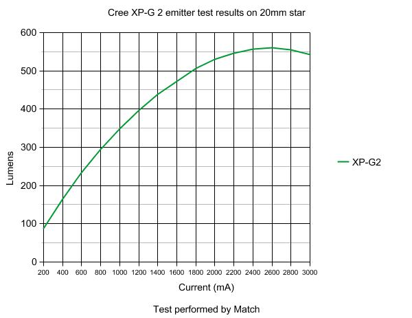
Consider a graphed curve of the voltage input and the light output.
The maximum power an LED can output is generally considered to be the point at which increasing power results in less output per power, i.e, the efficiency begins to plummet. Not the top of the curve which is where increased power equals zero increased light, but the point where slope begins to change.
Heres an example.

In my case, the normal safe point will be an area well below the curve, perhaps the 400 lumen point on this graph, the maximum will be about 525 lumens, and only really worked out for the sake of knowing that THAT is what the maximum is. Its not the true maximum, but, that is probably a tad higher than the LED is designed to run at, that point and beyond, may shorten the lifespan of the LED as well as possibly throwing off a slightly different color of white.
The safe point is an easily determined safe point you can probably find by feel/eyeing it. However i will be cross examining the the output results with some sort of photo-voltaic or photo-diode sensor reading on the scope to find the exact values, since no spec sheets exist for these LED strips.
Ill be sure to explain things in a way most people can comprehend, since im positive that 99% of people who are going to need this information are not going to know enough about electronics to confidently disassemble a $3000 tablet monitor
